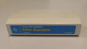
Retro: Editor/Assembler Module (TI-99/4A)

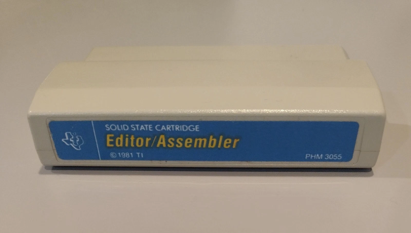
TI-99/4A Editor/Assembler Module (front)
1. Introduction
The Editor/Assembler cartridge for the TI‑99/4A transformed the machine from a consumer home computer into a self‑contained development environment by combining an on‑cartridge menu and utilities with disk‑resident editor, assembler, linker and debugger programs. The module let hobbyists and small developers write, assemble and debug native TMS9900 code directly on the 99/4A rather than relying on expensive minicomputer toolchains, and it shipped with an unusually large printed manual and example sources that make it one of the best‑documented pieces of TI home‑computer software.
2. Hardware and distribution
The Editor/Assembler is implemented as a GROM command module that provides menus, vectors and small helper routines; the full editor, assembler, linker and loader are supplied on a companion floppy disk and are loaded into the system RAM when invoked. The cartridge therefore depends on the TI Peripheral Expansion Box (PEB), at least one disk drive and the 32K RAM expansion to run the full toolchain on real hardware.
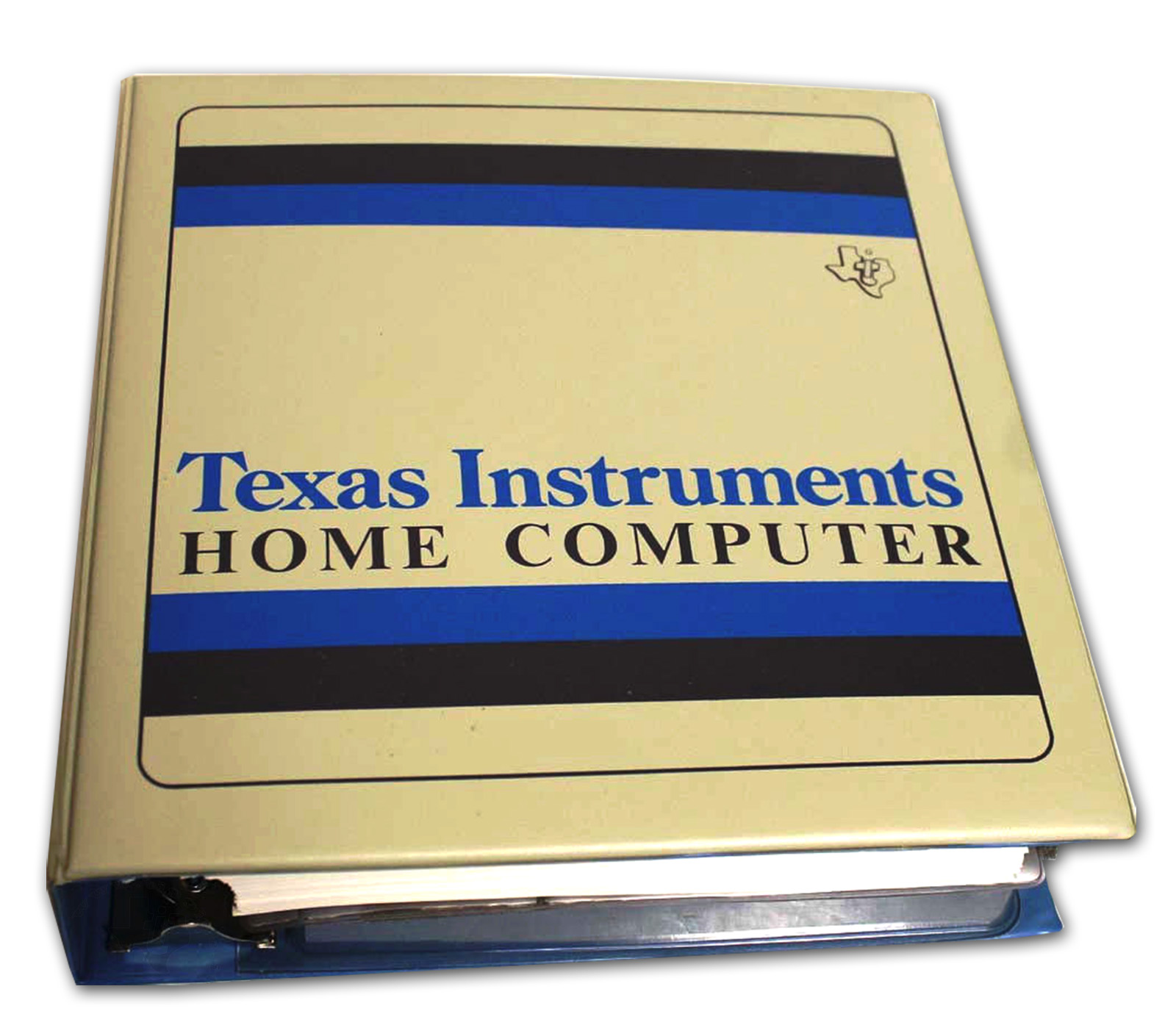
TI distributed the module as a two‑part package: the GROM cartridge (the visible “module”) plus a floppy disk containing the EDIT1 program and the assembler/linker binaries, together with a thick printed manual that documents both the Editor/Assembler user interface and the underlying TMS9900 instruction set and file formats. That manual and the companion disk images are preserved in multiple online archives and community compendia, which are useful primary sources for reproducing workflows or quoting exact file‑format details.
3. Editor/Assembler module: features and UX
Menu and program model. On power‑up the cartridge presents a simple menu (Edit, Assemble, Load & Run, Run, Run Program File) and dispatches to the disk‑resident programs via GROM vectors; the GROM itself contains a small linking‑loader and utility routines (POKEV/PEEKV, file helpers) used by the disk software. This split—GROM for UI and helpers, disk for heavy code—keeps the cartridge small while allowing a full‑featured toolchain to run in expanded RAM.
Editor UX. The editor supports two complementary modes: Edit Mode for direct typing and line editing, and Command Mode for higher‑level operations (find/replace, move/copy/delete, load/save/print). The on‑screen window is a 40×24 text viewport with cursor keys enabled, function‑key shortcuts for insert/delete and tab stops, and command‑line prompts for parameterized operations; later community revisions added optional 80‑column support. These features make the editor unusually capable for an on‑target cartridge editor of the era.
Assembler, linker and file formats. The assembler produces tagged‑object (DF80) files and the module’s linking loader understands those tags to resolve symbols and relocations; the editor can save source in DV80 (Div/Var 80) format or object in DF80 format. The manual documents the DF80 tagging conventions and the loader’s behavior (including how to avoid “undefined symbol” errors), which is essential reading when assembling multi‑module projects on the 99/4A.
Debugger and runtime tools. The Editor/Assembler package includes an on‑target debugger that can inspect and modify CPU RAM, VDP memory and GROM, view and change the workspace registers and status, set and clear breakpoints (limited number), and manipulate CRU bits. The debugger integrates with the module’s load interrupt vector so it can be reentered on load interrupts, enabling an interactive edit/assemble/debug cycle entirely on the machine. Community reimplementations and later module revisions preserved and extended these debugger commands.
Documentation and example code. TI shipped the module with an extensive manual that includes a TMS9900 instruction reference, system internals, and example programs; notably, TI also released the full source for at least one commercial title in the package, which has been repeatedly cited by historians and community archivists as an unusually generous disclosure for the period. The manual and example sources remain the authoritative references for the Editor/Assembler’s UX and file formats.
4. How the module works technically
The Editor/Assembler module combines a small GROM command logic in the cartridge with larger programs that are loaded from disk into expanded RAM. That split lets the cartridge remain compact while providing a full toolchain (editor → assembler → linker → loader → debugger) that runs directly on TI‑99/4A hardware.
Module architecture: GROM + disk + RAM
- GROM cartridge — contains the initial menu, vectors and helper routines (for example I/O helpers, PEEK/POKE vectors, and routines to invoke disk programs). The GROM stays resident and dispatches user commands to the disk‑resident modules.
- Disk programs — the editor, assembler, linker and larger parts of the debugger live on floppy disk and are loaded into expanded RAM when started (typically the 32K RAM in the PEB). This allows a richer interface and faster execution than if everything were stored in GROM.
- Expanded RAM and PEB — the module requires the Peripheral Expansion Box (PEB) and RAM expansion because the assembler and linker need more working memory than the base system provides; the PEB also supplies the disk controller and file I/O interface.
File formats and the loader
- Source and object formats — the editor saves source in a format adapted to the 40‑column display (the documentation refers to DV80 record types), while the assembler produces tagged object records (DF80‑style tags) that carry symbol, relocation and segment information.
- Linking loader — the loader understands the tagged object format and resolves symbols and relocations when linking multiple modules; it can produce memory images ready to execute or program files for later loading. The loader uses GROM vectors for I/O and to integrate with the debugger.
Memory map and workspace interaction
- TMS9900 workspace model — the TMS9900 uses a workspace pointer that points to a block of words in main memory serving as the CPU’s register file. The editor/assembler and debugger must work with this model: the debugger displays and edits workspace words, and the loader sets the WP appropriately when loading a program.
- Use of VDP and GROM space — some editor buffers and screen output use VDP memory, while GROM remains reserved for vectors and helper routines; understanding the difference between CPU memory, VDP memory and GROM space is essential for correct loading and debugging.
Debugger and loader integration
- Interactive debugging — the package includes a debugger that can view and modify RAM, access workspace registers, set and clear breakpoints (a limited number), and manipulate CRU bits. The debugger is integrated with the loader so it can be entered during program load or invoked manually.
- Interrupt vectors and handoff — GROM defines vectors that disk programs call; this lets the loader and debugger take control without modifying the system ROM.
Typical workflow (technical steps)
- Edit — write source in the editor running in RAM; the editor manages lines, search/replace and file operations.
- Assemble — the assembler reads source and emits tagged object records; relocations and symbols are encoded as tags.
- Link — the linking loader reads one or more DF80 objects, resolves symbols and relocations, and builds an executable memory image.
- Load & Run / Debug — the loader sets WP and PC, places the program in memory and starts execution; if debugging is enabled, control passes to the debugger to halt execution, inspect registers and memory, and return to the editor.
Implementation nuances and practical consequences
- Performance — because the register words are stored in main memory, operations that frequently change WP or use indirect addressing can be slower than on CPUs with internal register files; the toolchain and manual show idioms that mitigate these costs.
- Relocations and tags — the tagged object format supports modular linking but requires strict adherence to naming and tagging conventions; mistakes produce “undefined symbol” errors or incorrect relocations.
- CRU and peripherals — many system and I/O operations on the TI‑99/4A use CRU bit addressing; assembler output and loader behavior must supply correct CRU addresses and masks for peripheral control code.
Tips for reproduction and emulation
- On real hardware — provide a PEB, 32K RAM and a disk drive; load the cartridge, open the menu and load the disk programs in the documented order.
- In an emulator — use a disk image and configure the emulator to emulate the PEB and RAM expansion; verify the emulator correctly implements GROM vectors and CRU access, since incorrect emulation can change loader or debugger behavior.
Short technical summary: GROM supplies the UI and vectors; disk stores the heavy modules; 32K RAM/PEB enables execution of the tools; DF80 tagged objects and the linking loader provide modularity; the debugger operates directly on the workspace and CRU.
5. TMS9900 CPU: history and context
The TMS9900 was introduced by Texas Instruments in 1976 as one of the first single‑chip 16‑bit microprocessors, designed to bring the architecture of TI’s 990 minicomputer family into a microprocessor form.
Origins and design goals
- Minicomputer heritage. The TMS9900 implements the TI‑990 minicomputer architecture on a single chip, carrying over design choices intended for multi‑tasking and real‑time systems rather than for minimal‑cost home micros.
- Workspace register model. Instead of a large set of internal registers, the CPU uses a workspace pointer (WP) that references 16 general‑purpose registers stored in main memory; changing WP performs a very fast context switch because the CPU simply points to a different memory block for its register file. This model favored fast task switching in systems with fast memory but made ordinary register access slower compared with CPUs that kept registers on‑chip.
Packaging, market positioning, and early adoption
- Physical package and cost. The TMS9900 was supplied in a 64‑pin DIP to expose the wide address/control signals required by the architecture; that larger package and TI’s positioning made the chip relatively expensive compared with contemporaries in smaller packages.
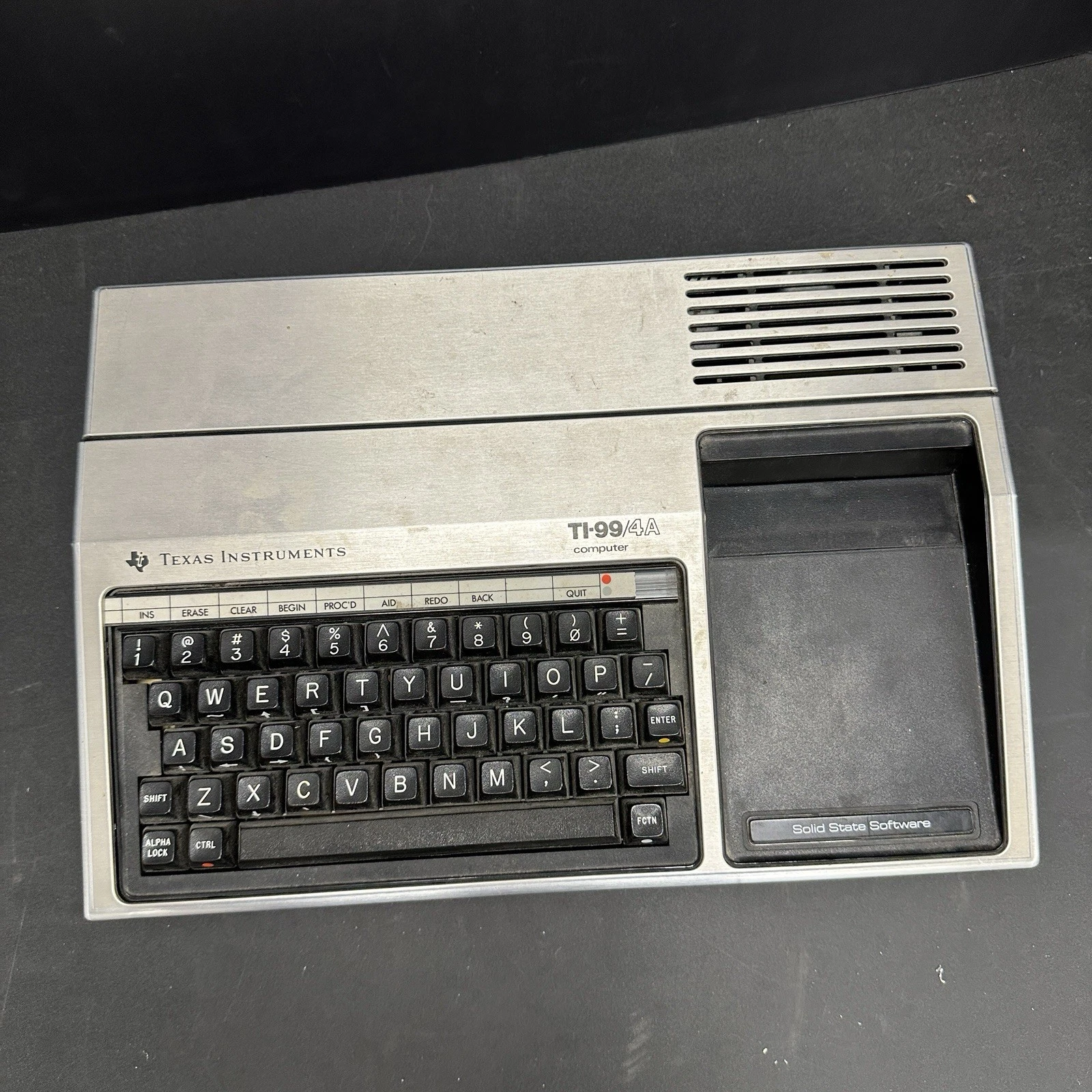
- Primary customers. TI used the chip internally across product lines and in its own systems; the most visible consumer adoption was the TI‑99/4 and TI‑99/4A home computers, which used the TMS9900 as their CPU. Outside TI’s ecosystem the 9900 saw relatively few design wins.
Technical tradeoffs and consequences
- Performance tradeoff. Mapping registers into main memory simplified context switching and supported the minicomputer heritage, but on systems with slower DRAM (typical of many microcomputer designs) the memory‑backed register file reduced raw instruction throughput versus processors with internal registers.
- I/O model and CRU. The TMS9900 included a CRU (Communication Register Unit) for bit‑level I/O operations and supported the XOP (extended operation) mechanism for vendor‑defined services, features that fit well with TI’s peripheral and system designs.
Market fate and legacy
- Limited mainstream success. As the microcomputer market moved toward lower‑cost 8‑bit parts and later toward other 16/32‑bit designs (Intel 8086 family, Motorola 68000), the TMS9900’s niche narrowed; TI shifted focus to specialized 32‑bit and DSP families (for example the TMS320 series) rather than pushing the 9900 as a mainstream microprocessor.
- Enduring influence. The workspace concept and CRU/XOP ideas persisted in TI’s internal designs and in specialized applications; the TMS9900 also remains historically important because it powered the TI‑99/4A, a widely sold home computer whose development tools (notably the Editor/Assembler) and software ecosystem are still studied by retrocomputing communities.
Short timeline
- 1976 — TMS9900 introduced as a single‑chip 16‑bit implementation of the TI‑990 architecture.
- Late 1970s–early 1980s — Used in TI systems and in the TI‑99/4A home computer; broader market adoption limited by cost and packaging.
- Mid‑1980s onward — TI pivots to DSPs and other specialized processors; the 9900 architecture survives in niche and embedded roles.
6. TMS9900 technical specs quick reference
The TMS9900 is a single‑chip 16‑bit microprocessor introduced by Texas Instruments in 1976, implementing the TI‑990 minicomputer register/workspace model and including CRU bit I/O and XOP extended‑operation support.
| Attribute | Specification | Typical TI‑99/4A value | Notes |
| Data width | 16‑bit | 16‑bit | Word‑oriented architecture. |
| Address space | 16‑bit logical (64 KB) | 64 KB | Word addressing with byte access conventions. |
| Register model | Workspace pointer + 16 memory registers | WP + R0–R15 in RAM | Registers are stored in main memory pointed to by WP. |
| Internal registers | PC, ST, WP, INTMASK, others | PC, ST, WP | Small set of internal control registers. |
| Instruction set | Dual‑operand, single‑operand, CRU, XOP, shifts, RTWP | Full TMS9900 ISA | XOP provides vendor‑defined extended operations. |
| CRU I/O | Bit‑addressable CRU (Communication Register Unit) | CRU used for peripheral control | Supports single‑bit and multi‑bit CRU ops. |
| Clock range | Vendor dependent; system dependent | ~3.0–3.3 MHz in TI‑99/4A | TI‑99/4A system clock yields ~3.0–3.3 MHz CPU timing. |
| Package | 64‑pin DIP (typical) | 64‑pin DIP | Large pin count for address/control signals. |
| Introduced | Year | 1976 | Single‑chip implementation of TI‑990 minicomputer. |
| Special features | Workspace switching; XOP; CRU | Fast context switch via WP | Workspace pointer enables rapid task switching. |
Key technical notes
- Workspace pointer model — WP points to a block of 16 words in main memory that serve as the CPU’s general registers; changing WP switches the entire register file quickly.
- CRU and peripheral I/O — the CRU provides bit‑level I/O instructions and addressing that TI used extensively for peripheral control on the 99/4A.
- XOP extended operations — XOP is an opcode mechanism that vectors to vendor‑supplied handlers (used for system services and optional extensions).
- Performance tradeoffs — because the general registers live in main memory, raw instruction throughput depends heavily on memory speed; this design favored fast context switching and minicomputer semantics over minimal‑cost silicon.
7. Architecture and instruction set — detailed overview
TMS9900 is a **16‑bit, memory‑to‑memory CISC processor** that implements the TI‑990 minicomputer architecture on a single chip. The design favors fast context switches and system services over maximum per‑instruction throughput.
Basic registers and workspace model
- Internal registers: Program Counter (PC), Status register (ST) and Workspace Pointer (WP).
- Workspace: WP points to a block of 16 consecutive 16‑bit words in main memory that serve as the general registers R0–R15. Changing WP effectively switches the entire register file, enabling very fast context switches (useful for interrupts and task switching).
- Implication: because the “registers” reside in RAM, register accesses depend on memory speed; on systems with slower DRAM this reduces raw throughput compared with processors that keep registers on‑chip.
Addressing modes (overview)
- Workspace register addressing — direct `Rn` access (fast when the workspace is in fast memory).
- Workspace indirect — `(R)` reads/writes via the address stored in a workspace register.
- Workspace indirect auto‑increment — `(R)+` uses the address in the register and then increments it; useful for iterating through arrays.
- Symbolic (direct) addressing — `@label` for direct memory references.
- Indexed addressing — `@table(R)` for table/indexed accesses.
- Immediate and PC‑relative — immediate constants and relative branches.
- CRU relative addressing — specialized addressing for bit‑level I/O via the CRU unit.
Instruction classes and key operations
- Dual‑operand instructions — `MOV`, `ADD`, `SUB`, `CMP`, etc.; source and destination may use different addressing modes (for example `(R)+` → `Rk`). These are the primary forms for data movement and arithmetic.
- Single‑operand instructions — `CLR`, `INC`, `DEC`, `NEG`, and similar operations on one operand.
- Shifts and rotates — arithmetic and logical shifts (`SRA`, `SRL`, `SLA`) that affect status bits.
- CRU instructions — bit‑level I/O (set/clear/test single CRU bits and multi‑bit CRU operations) designed for peripheral and control‑line handling; CRU is central to TI systems.
- XOP (Extended Operation) — an opcode mechanism that vectors to vendor‑defined handlers; used for system services and optional extensions.
- RTWP (Return Workspace Pointer) — instruction to restore the previous workspace on subroutine return, important for efficient context switching.
Examples and idioms (short, illustrative)
Switching workspace (context switch):
asm

LI   R0, >2000    ; load address of new workspace into R0 (conceptual)
MOV  R0, WP       ; set WP (assembler provides the appropriate encoding)
Load via indirect workspace register:
asm

MOV  @R1, R2      ; R2 := [R1]  (memory indirect through workspace register R1)
Setting a CRU bit (conceptual):
asm

SB   CRUaddr      ; set bit at CRU address
CB   CRUaddr      ; clear bit at CRU address
Note: exact mnemonics and encodings vary by assembler; consult the datasheet when publishing.
CRU and XOP — practical consequences
- CRU (Communication Register Unit) lets software address individual peripheral bits without reading/writing whole bytes or words; this is efficient for typical TI‑99 I/O tasks (keys, control lines, DSR interface). The TI‑99/4A loader and debugger make heavy use of CRU.
- XOP provides a way to add system calls or vendor extensions: an XOP instruction vectors to a handler table in low memory, allowing new operations without changing the base ISA.
Performance, timing, and practical consequences of the design
- Memory dependence: because registers live in RAM, memory cycle time directly affects instruction execution; on TI‑99/4A hardware some sequences are slower than on CPUs with internal register files.
- Timing details: the datasheet contains instruction timing tables and pin/timing specifications needed for precise optimization and interfacing; consult it for cycle counts and signal timing.
Common programming practices and optimizations
- Minimize WP switches where possible; prefer workspace‑indirect addressing over frequent WP changes.
- Use `(R)+` for loops** and array traversal — auto‑increment reduces instruction count and simplifies loop code.
- Use XOP for system services when interacting with complex system routines (for example, DSR disk calls on TI systems).
Short subroutine skeleton (conceptual)
asm

; caller:
BL   @subroutine   ; branch and link (conceptual)

; subroutine:
subroutine:
BLWP @new_workspace ; switch to new workspace and link

; ... body uses R0..R15 ...
RTWP                ; return and restore previous workspace
Verify actual pseudo‑mnemonics and vectors in your assembler and the TMS9900 datasheet.
Concise synthesis: TMS9900 brings minicomputer concepts (memory‑resident workspace, CRU, XOP) to a microprocessor, trading raw per‑instruction speed for very fast context switching and flexible system services; mastering addressing modes and workspace‑indirect idioms is essential for efficient code.
8. Practical development workflow
This section describes a repeatable workflow for developing software for the TI‑99/4A using the Editor/Assembler module on real hardware and alternative approaches (cross‑development and emulation). It focuses on concrete steps, required tools, common pitfalls, and practical tips for editing, assembling, linking, loading, and debugging.
Overview of the workflow
- Goal — write TMS9900 source, assemble into tagged object records, link modules into an executable memory image, and test/debug on real hardware or in an emulator.
- Two main approaches — on‑target (everything runs on the TI‑99/4A + PEB + 32K + disk) and cross‑development (author and assemble on a modern PC, then transfer binaries to an emulator or real machine).
Required equipment and resources (on‑target)
- TI‑99/4A with the Editor/Assembler GROM cartridge inserted.
- Peripheral Expansion Box (PEB) with at least one floppy drive.
- 32K RAM expansion installed in the PEB (assembler/linker require it).
- Disk image or floppy containing the EDIT/ASSEMBLE programs and the manual.
- Cables, power, and any disk‑image transfer tools if you plan to move images between PC and real disks.
On‑target step‑by‑step workflow
- Prepare the environment — insert the Editor/Assembler cartridge, attach the PEB and disk drive, power on, and launch the Editor from the cartridge menu.
- Write source — use Edit Mode for line editing and Command Mode for find/replace, move/copy/delete and file operations; save source in DV80‑compatible format.
- Assemble — run the assembler from the menu; it emits DF80 tagged object records. Inspect and fix any assembler errors.
- Link — load one or more DF80 objects into the linking loader; the loader resolves symbols and relocations and produces an executable memory image. Watch for “undefined symbol” messages.
- Load & Run — the loader sets WP and PC, places the program in memory and starts execution; use Run or Load & Run as appropriate.
- Debug — enter the debugger to inspect workspace words, RAM, VDP and GROM, set breakpoints, and manipulate CRU bits; return to the editor, fix code, and repeat assemble/link/load.
- Archive — save source and object files to disk or disk‑image for later reproduction.
Cross‑development workflow (modern PC → emulator / hardware)
- Why use cross‑development — faster editing, modern tooling, version control, automated builds, and easier backups.
- Typical steps — author code in a modern editor; use a cross‑assembler to produce DF80 or compatible binary images; transfer the image to an emulator or write it to real media; test in emulator and then on hardware when stable.
- Important — ensure the cross‑assembler outputs the exact format the TI loader expects (DF80 or a compatible binary image).
Debugging and iteration
- Fast cycle — expect frequent edit → assemble → link → load → run/debug iterations.
- Using the debugger — verify WP, PC, status bits and CRU; set breakpoints immediately before suspect code.
- Error triage — resolve link errors first, then check workspace initialization and CRU addresses; relocation mistakes often produce strange runtime behavior.
- I/O testing — isolate CRU and VDP routines into small test programs to validate peripheral behavior before integrating them.
File formats, tagging and linking conventions
- DF80 (tagged objects) — contains symbols, relocation records and segment info; the loader expects strict tag formatting.
- DV80 (source records) — editor format tuned to the 40‑column display; be careful with control characters and line endings.
- Recommendation — document module and symbol naming conventions to avoid link conflicts.
Performance considerations and optimizations
- Minimize WP switches — changing the workspace pointer is relatively expensive; group work that requires a different workspace.
- Use (R)+ for loops — auto‑increment addressing reduces instruction count for array traversal.
- Manual profiling — measure critical loops and optimize according to datasheet timing (memory latency has a large effect).
Emulation and reproducibility
- Emulator benefits — faster iteration and easy disk‑image management; verify the emulator correctly implements GROM vectors and CRU behavior.
- Transfer to real hardware — use compatible disk images or physical transfer methods; always perform final tests on real hardware when possible.
Common pitfalls and how to avoid them
- Missing 32K RAM — assembler/linker will not run without the RAM expansion; confirm PEB configuration.
- Incorrect DF80 tags — strict formatting is required; small tag errors cause linking failures.
- Wrong CRU addresses — incorrect CRU masks or addresses lead to unpredictable I/O; test CRU code separately.
- Emulator/hardware differences — some emulators omit subtle hardware behaviors; final verification on real hardware is recommended.
Pre‑release checklist
- Source saved in DV80 and in a modern VCS if using cross‑development.
- DF80 or executable image tested in emulator and on real hardware.
- Documentation of required hardware configuration (PEB, 32K, disk).
- Small test suite: workspace init, CRU I/O test, VDP output test, and main program run.
9. Conclusion and legacy
The Editor/Assembler cartridge and the TMS9900 CPU together represent a distinctive chapter in early home‑computer history: a commercially shipped, on‑target development environment built around a 16‑bit minicomputer heritage. The module made native assembly development accessible to hobbyists and small developers on the TI‑99/4A, while the TMS9900’s workspace model and CRU/XOP facilities embodied design choices aimed at real‑time and multi‑tasking systems rather than raw per‑instruction speed.
Why it matters today
- Practical on‑target tooling. The Editor/Assembler showed that a consumer machine could host a usable, integrated edit/assemble/link/debug toolchain without offloading development to expensive minicomputers. That on‑target workflow shaped how many TI developers learned low‑level programming.
- Architectural distinctiveness. The TMS9900’s memory‑resident register file (workspace) and CRU bit I/O are unusual among microprocessors of the era; they force different idioms and optimizations and therefore offer modern readers a useful counterpoint to register‑centric ISAs like the 6502 or 68000.
- Educational value. The module’s manual, examples and debugger make the platform an excellent teaching case for systems programming, linking/relocation concepts, and the practical tradeoffs between ISA design and system performance.
Legacy in retrocomputing and preservation
- Community interest. Enthusiasts preserve disk images, manuals and source examples; the Editor/Assembler remains a frequent subject of archival projects, emulator support and reproduction hardware because it documents real development practices.
- Influence on tooling expectations. The package anticipates later expectations for integrated development environments: edit, assemble, link and debug in a single, discoverable workflow.
- Research and reuse. Historians and implementers study the DF80 tagged‑object format, the loader semantics and the debugger hooks to reproduce faithful emulation and to port or reimplement the toolchain for modern cross‑development.
Practical lessons for modern developers and historians
- Design tradeoffs matter. The workspace model highlights how architectural choices (fast context switching vs. register throughput) ripple through assembler idioms, linker design and debugger features.
- Tooling is part of the platform story. A machine’s software ecosystem—especially its development tools—shapes what software gets written and how maintainable it is. Preserving tools is as important as preserving hardware.
- Documentation is invaluable. The Editor/Assembler’s extensive manual and example sources are why the module remains teachable and reproducible decades later.
Takeaway
The Editor/Assembler and the TMS9900 together are more than period curiosities: they are a compact case study in how CPU architecture, I/O models and developer tooling co‑evolve. For anyone interested in systems programming, retro toolchains, or the history of home computing, they reward study with concrete lessons about tradeoffs, ergonomics and preservation.
Dejan Vasic
Compact TMS9900 reference table
| Attribute | Value |
| CPU family | TMS9900 (Texas Instruments) |
| Data width | 16‑bit |
| Introduced | 1976 |
| Typical clock (TI‑99/4A) | ~3.0–3.3 MHz (system dependent) |
| Register model | PC, ST, WP internal; 16 general registers stored in external memory (workspace) |
| Address space | 64 KB logical (word/byte addressing; big‑endian) |
| Special features | CRU bit I/O, XOP (extended opcodes), memory‑mapped workspace for fast context switch |
| Notable instruction classes | Dual‑operand, single‑operand, CRU ops, shifts, XOP, RTWP. |